Brown & Michaels
How do I read a patent? - the Drawings
"The applicant shall furnish a drawing where necessary for the understanding of the subject matter to be patented." - 35 USC 113
Most US patents will have drawings. It is unusual, but not unheard of, for a patent to omit drawings - for example, a chemical compound or steel composition, or a pure method of doing something, might not need drawings. The standards for patent drawings can be found in the Manual of Patent Examining Procedure (MPEP), section 608.02
There are usually a number of drawings, numbered from "fig(ure) 1" up. Sometimes a figure will be broken up into several sub-figures, or there may be a number of figures showing the same thing at different stages. In these cases, it is traditional to number these sub-figures or alternate figures with appended letters: fig. 1A, fig. 1B, etc.
Sometimes it is necessary to show how things were done before the invention was made. Such figures will be labeled as "Prior Art", and they do not form part of the patented invention.
In a drawing figure, each part of the invention which needs to be discussed will be "called out" with a reference number, usually connected to the part with a line. If a reference number is underlined (as in 3, in the cut-away view below), it refers to the part on which the number is superimposed. If the line from the reference number appears to point at nothing in particular (i.e. 10 in the 3D view or 7 in the cut-away view), it usually refers to the device as a whole.
Traditionally, if the same part appears in more than one figure, the same number is used to refer to the part on all views. In the past, if there were more than one instance of a part, or the part is shown in more than one place, the different occurrences of the part would be distinguished with "primes" or apostrophes - 71, 71', 71" and so on. This is seen as fairly old-fashioned today, and it's more common now to use 71a, 71b, 71c, etc. Older patents may also use letters in place of reference numbers, but this, too, is considered old-fashioned.
There are several kinds of drawing:
Perspective or 3D View
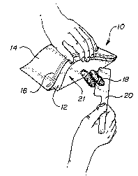
This kind of view shows a device as it might look if seen in three dimensions. Traditionally, the 3D view is from above and right or left of center.
Section or Cut-away View
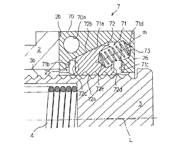
The section or cut-away or cut-through shows the invention as if it had been sliced through with a knife. Usually, there will be a perspective or flat view of the device, and the place where the section is cut will be indicated by a dashed line with arrows showing the direction of the view.
The Exploded View
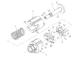
In this drawing, the coupling is shown with all of the parts pulled apart along the axis of the coupling. The "snaky" dashed line indicates that, to conserve space, the two halves were placed side by side, but that spring 7 and coupler 53 are really next to each other in line.
Block Diagram
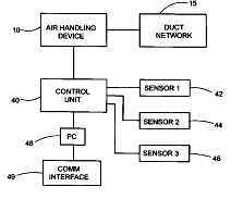
Block diagrams are used to show the various parts of a system in very general terms, and indicate the relationship of the parts. If the part is something which would be easily recognized, for example box 45 "PC", there will usually not be any more detail than that. If more detail about a part is required, then there will be another figure giving the detail.
Flowchart
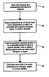
Method patents will often have flowcharts which give the steps of the method.
In case you were wondering, the USPTO has its Guide for Preparation of Patent Drawings available on the web in ZIP format (expands into an MSWord document). You can download it here - warning, it's 6MB in size!
<- Back to the Front Page - Ahead to the Specification ->
Back to "How to read a patent" main page